How to Replace a VT320 CRT With a Non-Original CRT
A Procedure in 10 Steps, for the Technically Capable
Disclaimer: this Howto describes a risky procedure that involves messing with the insides of electrical equipment, 110V or 240V mains voltage, a 18000 Volts power supply, and glass cathode ray tubes that can implode violently if dropped or hit at the wrong spot. THERE IS ABSOLUTELY NO GUARANTEE THIS PROCEDURE IS SAFE OR THAT IT WILL WORK. IF YOU INJURE OR ELECTROCUTE YOURSELF OR SOMEONE ELSE, DESTROY YOUR EQUIPMENT, OR BLOW UP YOUR HOUSE, IT IS *YOUR* PROBLEM!!! DON’T SAY I HAV’NT WARNED YOU!
A result of 10 or 15 years of constant operation, one of my old VT320 terminals had a clear case of dead CRT, with some signs of burn-in on top of that.
I took apart my old monochrome, ‘386 era (1990) EMC monitor and found out the CRT is exactly the same size and shape as that of the VT320.
I don’t think it is a coincidence, it makes sense that many monochrome CRTs from that era had the exact same shape and size.
This was reason enough to boldly attempt a replacement.
Note: if you don’t have a spare CRT, some methods can be attempted to revive the dark CRT, such as the ones here or here, or you can try and locate a Sencore Restorer.
What you’ll need:
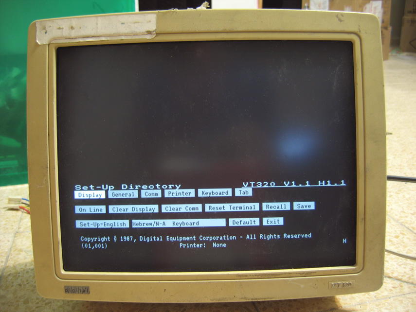
A dead-CRT VT320 terminal, and a Black-and-White (or Black-and-Green etc.) 12″ computer monitor:

You can see in the photo that the high-voltage connector (the one that looks like a vacuum suction cup) is on the ‘right’ on the VT320, but on the ‘left’ on the old monitor. The lead coming out from the flyback transformer is exactly the right length, so the old monitor CRT has to be flipped ‘upside-down’ so it would match the VT320’s connection scheme. Those CRTs are symmetrical for all practical purposes, so it’s not a problem.
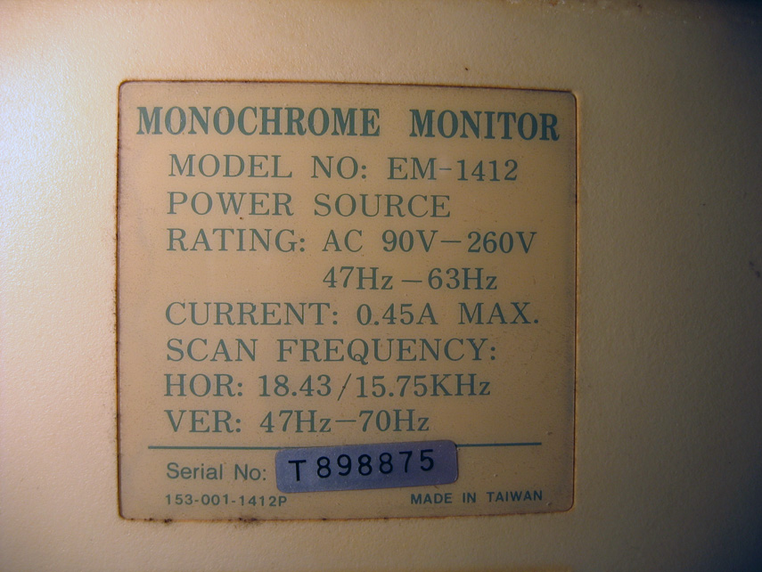
That’s what the old monitor label read:
If you can, try and verify that the old monitor’s CRT is not as bad as the one you’re trying to replace.
I have located and marked the relevant components of the VT320’s CRT for you:
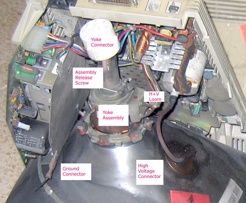
Step 1: Remove the monitor’s CRT and the VT320 CRT by releasing the four screws (one on each corner), the high voltage connectors, looms and yoke connector, as well as any grounding connectors.
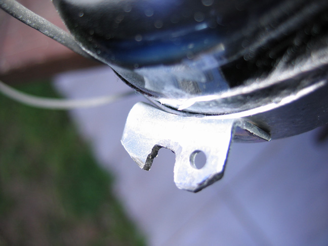
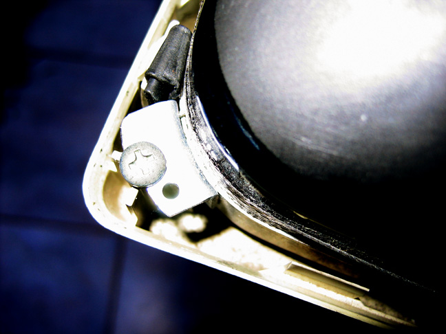
Step 2: Remove the retaining screw off the VT320’s CRT and gently pull out the yoke assembly. Do the same with the monitor’s yoke assembly. The retaining screws of the two assemblies are pictured below:


Step 3: slide the VT320’s original yoke assembly over the replacement CRT’s neck, keeping it straight with the CRT orientation, and carefully tighten the retaining screw – not too tight, the old plastic has been slowly cooking for years, it may be brittle. Don’t worry about the exact straight orientation, you can always (and probably will have to) re-orient the yoke assembly slightly to keep the picture nice and horizontal.
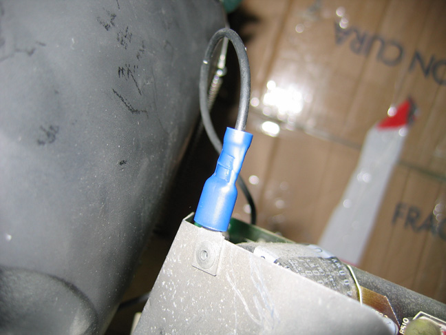
Step 4: I had to re-do the VT320 ground connector using a crimp-type quick-connect, because the old monitor’s ground connection used a different system. I simply chopped off the old monitor’s connector and crimped a blue female quick-connect as seen in the photo:
Step 5: if you are brave enough, hook everything up back again and see if this procedure is worth proceeding.
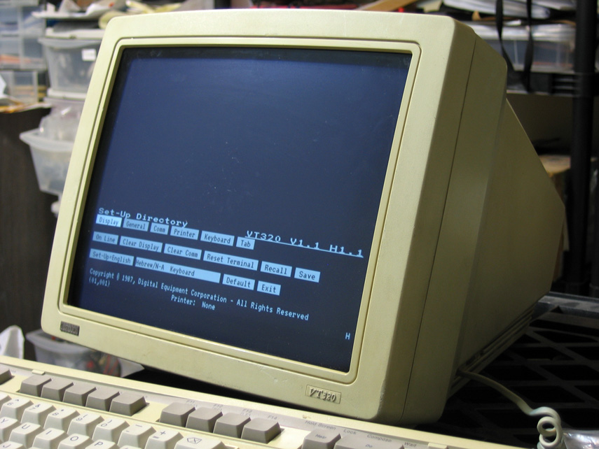
This is what I saw:
Even the focus was acceptable, considering the major CRT transplant the thing has just gone through:

After carefully adjusting the yoke assembly position, consulting the VT320 pocket service guide, and moving the jumper position from CLIN (Clinton was the original CRT brand) to PHIL (which stands for Philips), this is the result:
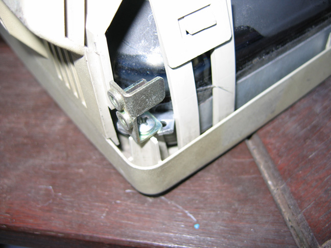
Step 6: check the metal lugs used to secure the CRT to the plastic frame of the monitor. The four metal lugs holding my replacement CRT in place are larger than the original VT320 lugs, and thus the replacement CRT cannot be fixed in place and the VT320 lid cannot be closed. The lugs seem secured pretty tightly to the glass, so I didn’t want to try and replace them completely.

After 20 minutes of chopping the edges and routing into the four metal lugs, this is what they look like:
Step 7: Now the screws fit nicely and the lid can be closed. Make sure you mount the brass part used to secure the plastic lid screws, there are 2 of these parts and they mount on the ‘bottom’ screws of the VT320. You should know anyway, you removed them in step 1.
Step 8: Make sure the picture is straight, linear and in focus, and close the lid.
Step 9: This was, after all, a junk VT320. So remove old stains and stickers; I used Eucalyptus oil which works incredibly well, without damaging any plastics, and some acetone where I had no other choice – as acetone is a bit too strong for using on the monitor’s cover.
Step 10: Admire your work!
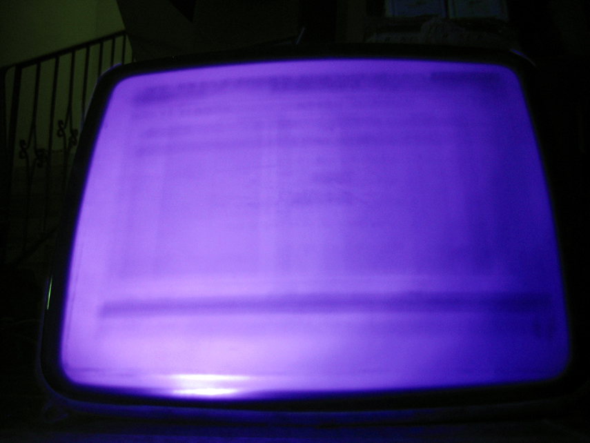
Just to satisfy my curiosity, I looked at the old VT320 tube under UV light, before heading to the recycle depot. The screen burn-in is clearly visible, the regions where the poor thing has shown the exact same text (or worse, inverse text) for many years are much darker than their surroundings.